
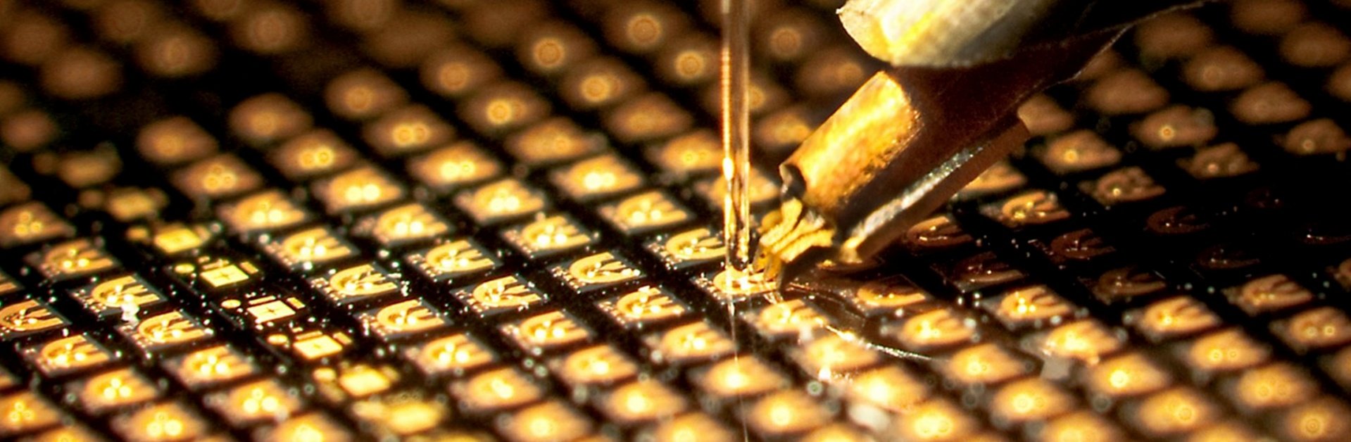
VCSEL Chip: Selection, Packaging and OEM Integration
A VCSEL chip is a compact semiconductor laser that emits light perpendicular to the wafer surface. This structure is different from an edge-emitting laser, where light exits from the side of the chip.
For an engineer selecting a VCSEL, that structural difference matters because it affects testing, packaging, array design and optical integration.
In practice, the terms VCSEL chip and VCSEL die are often used for the same bare semiconductor device after wafer processing and dicing. What matters more is the specification behind the name: wavelength, optical power, spectral behavior, beam characteristics, operating conditions and package requirements.
For OEM projects, these parameters should be defined before deciding whether a bare chip, packaged VCSEL or integrated module is the right starting point.
How a VCSEL Chip Is Built
A VCSEL is fabricated as a layered semiconductor structure, commonly on a GaAs-based platform for near-infrared wavelengths.
The optical cavity is formed vertically through the device structure. Semiconductor layers above and below the active region act as distributed Bragg reflectors, while the active region generates the optical emission.
Several manufacturing steps influence the final device characteristics, including epitaxial growth, lithography, etching, oxidation, metallization and wafer-level testing.
This vertical structure also makes it practical to test devices before the wafer is diced into individual chips.
For customers, however, the manufacturing process is usually less important than the electrical and optical parameters that come out of it.
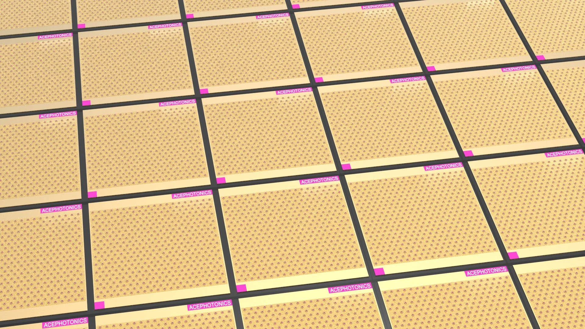
VCSEL Chip and VCSEL Die: Is There a Difference?
The two terms are frequently used interchangeably.
A VCSEL die normally refers specifically to the individual semiconductor die cut from the processed wafer.
A VCSEL chip is a broader commercial term and may also be used to describe the same bare device before it is assembled into a package.
The distinction becomes more useful when discussing the level of integration:
An OEM with established die-bonding and optical assembly capability may prefer a bare VCSEL chip. A customer developing a smaller production volume or a system with tighter mechanical requirements may find a packaged device easier to integrate.
Start With the Wavelength
The wavelength is usually one of the first parameters to define.
Different sensing systems operate in different spectral regions, and choosing a VCSEL chip simply because it has suitable output power is not enough if the wavelength does not match the optical system.
Some common directions include:
The exact wavelength requirement may be much narrower than the nominal wavelength shown on a product family.
For spectroscopy and atomic sensing, customers may also need to consider wavelength tolerance, tuning behavior and spectral characteristics.
For optical sensing, detector sensitivity and filter transmission may be more important.
Optical Power Should Be Defined by the System
Output power is easy to compare on a datasheet, but it should not be treated as an isolated performance score.
A system may need additional optical power because of:
optical losses
longer optical paths
beam expansion
receiver sensitivity
field of illumination
operating distance
duty cycle
Another system may achieve its target performance with lower optical power while placing tighter requirements on linewidth, beam divergence or wavelength stability.
For this reason, the useful question is not simply:
“What is the highest-power VCSEL chip available?”
It is:
“What optical power is required under the actual operating conditions of the system?”
That distinction becomes particularly important in precision sensing applications.
Spectral Requirements for a VCSEL Chip
Two VCSEL chips with similar wavelength and output power may still behave differently in a precision optical system.
Depending on the application, the specification may need to include:
single-mode or multimode operation
spectral linewidth
polarization
wavelength tolerance
current tuning behavior
temperature tuning behavior
side-mode characteristics
For atomic sensing and spectroscopy, these parameters can be central to device selection.
For general infrared illumination, the requirements may be less restrictive, while beam distribution, modulation or total optical output may become more important.
This is why the application should be defined before the VCSEL chip specification is finalized.
Beam Characteristics and Optical Integration
The light leaving a bare VCSEL chip still has to interact with the rest of the optical system.
Depending on the project, the VCSEL may be used with:
collimation lenses
micro-optics
microlens arrays
diffusers
diffractive optical elements
optical windows
other beam-shaping components
Beam divergence, emitting aperture and chip position therefore affect more than the laser itself.
They influence lens selection, alignment tolerance, module dimensions and the resulting illumination pattern.
If downstream optics have already been selected, their requirements should be included when choosing the VCSEL chip.
If the optical system is still being designed, the chip and optics can be evaluated together.
Temperature and Drive Conditions
VCSEL wavelength and optical output change with operating conditions.
The relevant temperature is not only the room temperature around the instrument. Drive current, duty cycle, package structure and heat dissipation can all influence the actual device temperature.
For a new design, it is useful to define:
Temperature control should be selected according to the application.
A general sensing system and a narrow-linewidth spectroscopy system may require very different thermal strategies even when they use VCSEL chips at similar wavelengths.
Bare VCSEL Chip or Packaged Device?
Buying a bare VCSEL chip gives the system designer the greatest freedom, but it also requires suitable semiconductor assembly capability.
Die bonding, wire bonding, thermal design, optical alignment and protection of the chip surface all become part of the customer's integration process.
A packaged VCSEL can reduce some of this work.
Common options include:
Bare Die
Suitable for customers developing their own package, optical assembly or chip-level system.
TO Package
Useful for laboratory systems, instruments and applications where a conventional laser package is preferred.
SMD Package
Suitable for compact PCB integration and automated assembly.
Non-Magnetic Package
An option for systems where reducing magnetic materials close to a sensitive measurement region is important.
Customized Package
Useful when the standard mechanical, optical, electrical or thermal configuration does not fit the system.
There is no universally better package type. The choice depends on the equipment around the VCSEL.
What Can Be Customized?
For an OEM project, customization should begin with a real system requirement rather than a broad request for a “custom laser.”
Depending on the project, a VCSEL chip or packaged device may be developed around requirements such as:
target wavelength
optical power
chip dimensions
aperture design
single-mode or multimode operation
spectral characteristics
beam divergence
package materials
optical window
electrical interface
thermal-control components
Not every project requires a new chip design.
Sometimes an existing VCSEL chip combined with a different package, optical window or thermal configuration is enough to meet the requirement.
That distinction is useful because chip development and package customization involve very different levels of engineering work.
What to Provide When Requesting a VCSEL Chip
A short list of system parameters usually makes technical evaluation more efficient.
For spectroscopy or atomic-sensing projects, providing the target atomic transition or absorption feature is also useful.
For imaging and illumination projects, working distance, field of view and downstream optics can help define the required VCSEL configuration.
From VCSEL Chip to an OEM Optical System
Choosing a VCSEL chip is ultimately an integration problem.
Wavelength and output power are the obvious starting points, but they do not describe the complete device. Spectral behavior, drive conditions, temperature, beam characteristics and packaging all affect whether the VCSEL will fit the final system.
Ace Photonics supports VCSEL chip design, semiconductor processing and package development for sensing, spectroscopy and other precision photonic applications. Available integration routes include bare die, TO, SMD, non-magnetic and customized package configurations.
For a new OEM project, defining the optical and mechanical requirements first is usually more useful than selecting a VCSEL chip from one headline specification.