
Vertical Cavity Design in VCSELs: How It Controls Performance
The vertical cavity is the central optical structure inside a Vertical-Cavity Surface-Emitting Laser, or VCSEL. It determines where optical resonance occurs and strongly influences the emission wavelength, threshold current, optical mode, beam characteristics and temperature behavior of the device.
Unlike an edge-emitting laser, in which light travels horizontally through the semiconductor chip, a VCSEL generates and amplifies light in a short cavity positioned perpendicular to the wafer surface. Light then exits through the top or bottom surface of the device.
A carefully designed vertical cavity must bring together several elements: two distributed Bragg reflector mirrors, an active region, current-confinement structures and electrical contacts. Small variations in layer thickness, composition, aperture size or temperature can change the final performance.
What Is a Vertical Cavity?
A vertical cavity is a short optical resonator formed between two reflective mirrors positioned above and below a semiconductor active region.
In a typical VCSEL, these mirrors are distributed Bragg reflectors, commonly known as DBRs. Each DBR contains alternating semiconductor layers with different refractive indices. The layers are designed to reflect light around a selected wavelength.
The active region sits between the upper and lower DBRs. When electrical current is applied, the active region generates photons. These photons travel vertically between the mirrors and pass repeatedly through the gain region.
When the optical gain becomes sufficient to overcome internal and mirror losses, laser oscillation begins. Part of the light then passes through the output mirror and leaves the device vertically.
DBRs do more than define the optical cavity. In semiconductor VCSEL structures, they may also contribute to electrical conduction, current confinement, thermal behavior and the crystalline foundation surrounding the active region. cal Cavity Components

These elements cannot be designed independently. For example, increasing DBR reflectivity may reduce optical loss but can also influence electrical resistance and heat removal. Changing the aperture can alter current confinement, optical confinement and modal behavior at the same time.
How a Vertical Cavity Produces Laser Light
The operating process can be summarized in five stages.
1. Current Injection
Electrical current enters the VCSEL through its contacts and flows toward the active region.
A current aperture or another confinement structure directs the current through a defined area. This helps determine the effective emitting diameter.
2. Photon Generation
Electrons and holes recombine in the active region, which commonly contains one or more quantum wells. This process generates photons around the design wavelength.
3. Optical Reflection
The photons travel vertically and are reflected by the upper and lower DBR mirrors.
The alternating high- and low-refractive-index layers in each DBR reinforce reflection around a selected spectral range.
4. Resonance and Stimulated Emission
Only wavelengths that satisfy the resonance conditions of the vertical cavity are strongly reinforced.
As photons repeatedly pass through the active region, they stimulate the generation of additional photons with related optical properties.
5. Surface Emission
The output-side DBR is designed to allow a controlled amount of optical energy to leave the cavity.
The resulting beam exits perpendicular to the wafer surface, producing the surface-emitting geometry that defines a VCSEL.
How the Vertical Cavity Controls Wavelength
The emission wavelength of a VCSEL is influenced by both the semiconductor gain spectrum and the optical resonance of the cavity.
The resonance condition depends on factors including:
Physical cavity length
Refractive index of the cavity materials
Thickness and composition of the epitaxial layers
DBR reflection phase
Active-region design
Junction temperature
Mechanical strain
The optical thickness of the cavity must support resonance near the intended wavelength. Because the cavity is very short, small deviations in layer thickness or material composition can shift the resonance position.
This is especially important for wavelength-sensitive applications such as spectroscopy, atomic clocks and atomic magnetometers. A nominal wavelength alone may not be sufficient. Engineers may also need to confirm:
Center-wavelength tolerance
Wavelength shift with current
Wavelength shift with temperature
Spectral width
Side-mode suppression
Mode behavior across the operating range
The cavity resonance and material gain also respond differently to temperature. Proper design must keep them sufficiently aligned across the required operating conditions.
The Role of DBR Mirrors
Distributed Bragg reflectors form the upper and lower mirrors of the vertical cavity.
A DBR normally consists of alternating layers with high and low refractive indices. Each layer is designed with an optical thickness related to the target wavelength. Reflections from the layer interfaces combine constructively, creating high reflectivity around the design band.
Important DBR design factors include:
Number of mirror pairs
Refractive-index contrast
Individual layer thickness
Material composition
Reflection bandwidth
Electrical resistance
Thermal resistance
Interface quality
Wafer-level uniformity
The bottom DBR is usually designed for very high reflectivity. The output-side DBR allows a controlled fraction of the light to leave the device.
Adding more DBR pairs may increase reflectivity, but it can also increase electrical and thermal resistance. The mirror design must therefore balance optical confinement with current injection and heat removal.
Thickness variation across the wafer can cause changes in resonance wavelength and device performance. DBR uniformity is consequently important not only for an individual VCSEL but also for wavelength consistency across a wafer and between production lots.
Active-Region Position and Optical Gain
The active region generates optical gain inside the vertical cavity. Its material composition and quantum-well structure are selected according to the required wavelength and operating characteristics.
The active region should be positioned where the standing optical field provides strong interaction with the gain material.
Important design considerations include:
Number of quantum wells
Quantum-well material composition
Gain peak wavelength
Position relative to the optical standing wave
Carrier confinement
Current density
Thermal behavior
The cavity resonance and gain spectrum must remain appropriately aligned. If they move too far apart because of temperature, current or manufacturing variation, threshold current may increase and output performance may decline.
Current Confinement and the Oxide Aperture
Many VCSELs use an oxide aperture to confine electrical current and help control the optical mode.
During fabrication, a high-aluminium semiconductor layer is selectively oxidized from the outside toward the center. The remaining unoxidized area forms a conductive aperture through which current can enter the active region.
The aperture diameter can affect:
Threshold current
Series resistance
Current density
Output power
Beam divergence
Transverse optical modes
Modulation bandwidth
Temperature stability
A smaller aperture may support stronger mode confinement and single-mode operation, but it can also increase electrical resistance and current density.
A larger aperture may support greater optical power, but it can allow more transverse modes to operate. Research on oxide-confined VCSELs shows that aperture placement and diameter can significantly influence efficiency, modulation performance and temperature behavior. e-Mode and Multimode Vertical Cavities
The lateral dimensions and confinement structures around the vertical cavity influence whether the VCSEL operates in a single transverse mode or multiple transverse modes.
Single-Mode VCSEL Design
Single-mode operation may be required for:
Atomic sensing
Spectroscopy
Precision measurement
Controlled beam coupling
Narrow spectral applications
Polarization-sensitive systems
A smaller emitting aperture or another mode-control structure may be used to suppress higher-order transverse modes.
However, single-mode performance should be checked across the complete current and temperature range. A VCSEL that appears single-mode at one operating condition may show different modal behavior at a higher current or temperature.
Photonic-crystal and aperture-based structures have also been studied for controlling transverse modes in VCSELs. imode VCSEL Design
Multimode operation may be acceptable or beneficial when higher total power is more important than single-mode beam characteristics.
Typical considerations include:
Total output power
Emitting-area size
Far-field distribution
Speckle behavior
Thermal roll-over
Array integration
Drive-current uniformity
The correct design depends on how the light will be collected, shaped or projected in the final system.
Thermal Effects in a Vertical Cavity
Electrical power that is not converted into optical output becomes heat. Because the active region and optical cavity occupy a small volume, junction temperature can rise as the drive current increases.
Temperature affects several parts of VCSEL operation:
Semiconductor gain spectrum
Cavity resonance wavelength
Threshold current
Output power
Series resistance
Optical efficiency
Mode behavior
Long-term reliability
As temperature increases, the emission wavelength generally shifts. Output power may eventually reach thermal roll-over, where additional current no longer produces a corresponding increase in optical power.
Thermal design must therefore include both the semiconductor structure and the package.
Important factors include:
DBR thermal resistance
Substrate thickness
Contact and metallization design
Aperture size
Mounting method
Die-attach material
Package thermal path
Ambient-temperature range
Continuous-wave or pulsed operation
Temperature performance should be evaluated under the intended drive conditions rather than inferred only from room-temperature measurements.
Manufacturing Factors That Affect Vertical Cavity Performance
The final VCSEL must reproduce the intended cavity design across individual devices, wafers and production lots.
Epitaxial Growth
The DBRs, cavity and active region are created during epitaxial growth. Layer thickness and composition must remain controlled across the wafer.
Local variation can lead to changes in wavelength, threshold current and output performance.
Lithography and Etching
Lithography defines the dimensions and alignment of contacts, mesas and other device structures.
Etching must expose the correct layers without unnecessarily damaging the optical or electrical structure.
Wet Oxidation
For oxide-confined VCSELs, oxidation conditions determine the aperture size and shape.
Oxidation time, temperature, layer composition and mesa geometry can all influence the final aperture.
Wafer-Level Testing
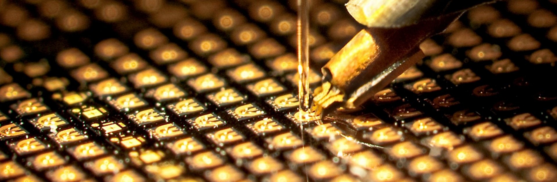
The surface-emitting structure allows optical and electrical testing before the wafer is divided into individual dies.
Wafer-level testing can support:
Wavelength mapping
Threshold-current measurement
Output-power measurement
Voltage testing
Device screening
Performance binning
Process monitoring
Testing requirements should correspond to the customer’s actual operating conditions whenever possible.
How Packaging Affects the Vertical Cavity
Although the vertical cavity is created within the semiconductor structure, packaging can still influence its performance.
Possible package-related effects include:
Mechanical stress on the die
Thermal resistance
Heat spreading
Optical-axis alignment
Window reflections
Back-reflection into the cavity
Electrical parasitics
Magnetic interference
Environmental exposure
For example, a window or lens positioned above the VCSEL can introduce reflection back toward the device. Mechanical stress from die attachment or thermal expansion can also influence the semiconductor structure.
The package should therefore be developed together with the optical, electrical and thermal requirements of the system.
Ace Photonics provides VCSEL die, TO-can, SMD, customized and non-magnetic package options at wavelengths including approximately 760 nm, 790/795 nm, 850 nm, 880 nm and 890/895 nm. re about:
Vertical Cavity Requirements by Application
Application names alone are not enough to define the cavity design. Two systems used for the same general application may require different wavelengths, apertures, power levels, beam characteristics or packages.
What to Confirm Before Requesting a Custom VCSEL
Customers should provide the following information before evaluating a custom vertical cavity design.
Defining these requirements early helps connect the vertical cavity design with the package and final system.
Vertical Cavity VCSEL Support from Ace Photonics
Ace Photonics develops GaAs-based VCSEL products for sensing, precision measurement, atomic systems and other photonic applications.
Project support may include:
Wavelength and power selection
Epitaxial and device-structure evaluation
Current-aperture design
Single-mode and multimode options
VCSEL die selection
TO-can and SMD packaging
Non-magnetic package development
Thermistor or TEC integration
Optical window and lens evaluation
Engineering samples
Application-specific modules
The development process should begin with measurable system requirements rather than only a general application description.
To discuss a project, provide the target wavelength, output power, optical mode, temperature range, package type and estimated quantity.
Contact Ace Photonics to request product information or discuss a custom vertical cavity VCSEL.
Frequently Asked Questions
What does vertical cavity mean?
A vertical cavity is an optical resonator oriented perpendicular to the semiconductor wafer. In a VCSEL, it is formed between two DBR mirrors with an active region positioned between them.
Is a vertical cavity laser the same as a VCSEL?
The term “vertical cavity laser” is often used informally to describe a VCSEL. The full name is Vertical-Cavity Surface-Emitting Laser.
However, a VECSEL, or Vertical-External-Cavity Surface-Emitting Laser, uses an external optical cavity and is a different device architecture.
Why are DBR mirrors used in a VCSEL?
DBR mirrors can provide high reflectivity around a selected wavelength while being integrated into the semiconductor layer structure. They form the optical resonator needed for vertical laser oscillation.
How does cavity length affect wavelength?
The optical length of the cavity determines which wavelengths satisfy its resonance conditions. Changes in physical thickness, refractive index, temperature or strain can therefore shift the resonant wavelength.
What does the oxide aperture do?
The oxide aperture confines electrical current to a defined area and also influences optical confinement. Its diameter affects threshold current, resistance, output power and transverse-mode behavior.
Why does VCSEL wavelength change with temperature?
Temperature changes the semiconductor refractive index, cavity resonance and material gain. These changes can shift the output wavelength and affect efficiency and modal performance.
Can the vertical cavity be customized?
The epitaxial structure, DBR design, active region, aperture and device geometry may be adjusted for a target wavelength, power, optical mode and operating environment. Feasibility depends on the complete requirements and expected production volume.
Does packaging change the vertical cavity?
Packaging does not normally change the original epitaxial layer design, but thermal resistance, mechanical stress, optical feedback and electrical conditions can affect how the cavity performs in the final system.