
What Is a VCSEL? Structure, Benefits and Applications
A VCSEL is a semiconductor laser that emits light vertically from the surface of a chip. The name VCSEL stands for Vertical-Cavity Surface-Emitting Laser.
Unlike an edge-emitting laser, which sends light through the side of a semiconductor die, a VCSEL emits light perpendicular to the wafer surface. This vertical structure supports compact devices, wafer-level testing, two-dimensional arrays and flexible integration with optical and electronic systems.
VCSELs are used in optical communication, 3D sensing, proximity detection, industrial sensing, LiDAR, spectroscopy, atomic clocks and quantum sensing. They are available as bare dies, packaged devices, arrays and integrated modules.
What Does VCSEL Stand For?
VCSEL stands for:
Vertical: Light travels perpendicular to the wafer.
Cavity: The laser contains a short optical resonator.
Surface-Emitting: Light exits through the top or bottom surface of the device.
Laser: Stimulated emission produces a coherent optical output.
The vertical cavity is the feature that distinguishes a VCSEL from a conventional edge-emitting laser diode.
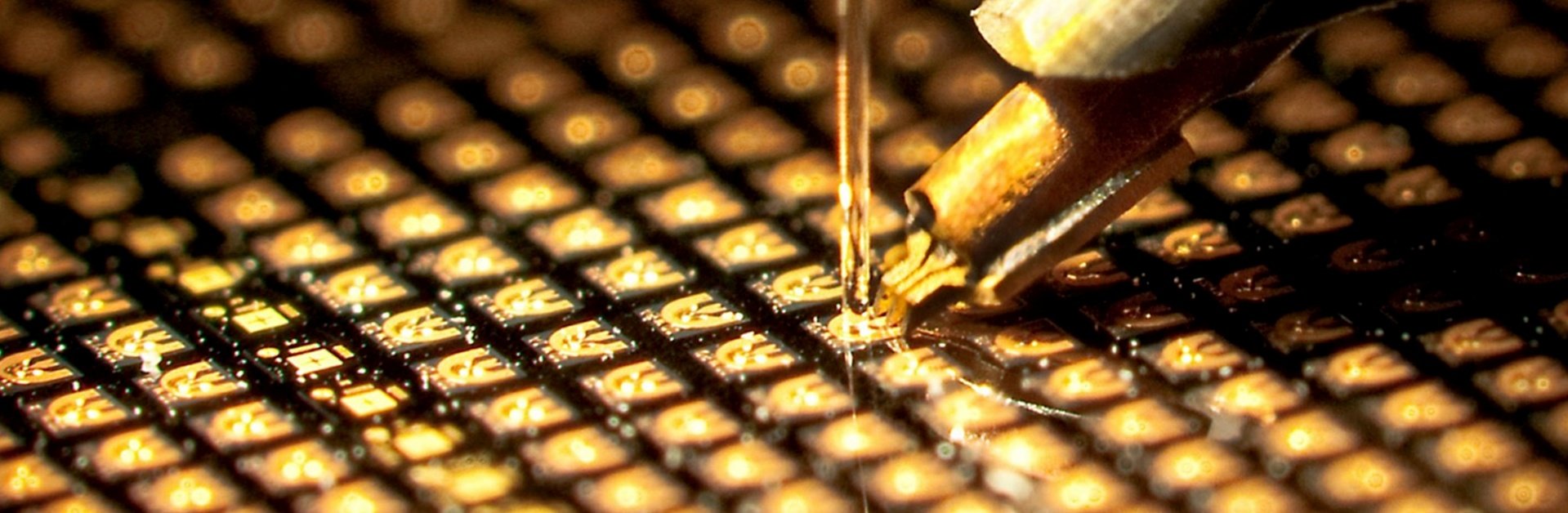
Because the light-emitting surface is accessible while the devices are still on the wafer, manufacturers can perform electrical and optical measurements before the wafer is separated into individual dies. This can support device screening, wavelength sorting and more efficient production.
How Does a VCSEL Work?
A VCSEL contains an active light-generating region positioned between two highly reflective mirrors called distributed Bragg reflectors, or DBRs.
When an electrical current passes through the device, electrons and holes recombine in the active region and generate photons. The photons move between the upper and lower DBR mirrors, building optical intensity inside the vertical cavity.
When the optical gain becomes high enough, laser light exits through the partially reflective mirror at the surface of the chip.
The basic operating process is:
Electrical current is injected into the device.
The active region generates photons.
The DBR mirrors reflect the photons through the cavity.
Optical intensity increases through stimulated emission.
A controlled portion of the light exits vertically from the surface.
The cavity dimensions, semiconductor materials, mirror design and current aperture all influence the wavelength, optical mode, output power and beam characteristics.
Main Parts of a VCSEL
Distributed Bragg Reflectors
A DBR is made from alternating semiconductor layers with different refractive indices. The thickness and composition of these layers are designed to reflect light around the target wavelength.
VCSELs generally require highly reflective mirrors because their optical cavities are much shorter than those of edge-emitting lasers. Small changes in epitaxial layer thickness can therefore affect the final emission wavelength.
Active Region
The active region normally contains quantum wells that generate light when carriers recombine. Its material composition is selected according to the required wavelength and device performance.
Current Aperture
Many VCSELs use an oxide aperture to direct electrical current through a defined area of the active region. Aperture size affects output power, threshold current, beam profile and transverse-mode behavior.
A smaller aperture may support single-mode operation, while a larger aperture or multiple emitters may be used when higher optical power is required.
VCSEL vs Edge-Emitting Laser vs LED
VCSELs, edge-emitting lasers and LEDs can all generate optical output, but their structures and operating characteristics are different.
A VCSEL is not automatically better than every edge-emitting laser or LED. The correct source depends on wavelength, output power, beam requirements, modulation speed, thermal conditions and system cost.
Main Advantages of VCSEL Technology
Surface Emission
The vertical output makes it possible to test devices while they are still on the wafer. It also supports top-side optical alignment and compact package designs.
Compact Device Structure
VCSEL dies can be small and can be integrated into SMD packages, TO-can packages, sensor assemblies and optical modules.
Circular Beam Profile
Many VCSELs produce a more circular beam than conventional edge-emitting laser diodes. This can simplify coupling to lenses, detectors and other optical components.
The actual divergence and beam profile still depend on aperture size, operating current and device design.
Two-Dimensional Arrays
Because light exits from the wafer surface, multiple VCSEL emitters can be arranged in rows or two-dimensional arrays.
Arrays may be used to increase optical power, illuminate a wider area or create patterns for structured-light and sensing systems.
Fast Modulation
VCSELs can be designed for rapid electrical modulation, making them useful for optical communication, time-of-flight sensing and other applications that require changing optical output.
The required modulation bandwidth should be confirmed at the operating current, temperature and package condition.
Wavelength Control
The emission wavelength is influenced by the epitaxial structure, cavity design, temperature and drive current.
Applications such as spectroscopy and atomic sensing may require tighter wavelength control than general illumination or proximity sensing.
Packaging Flexibility
VCSELs can be supplied as:
Bare dies
TO-can packages
SMD packages
Ceramic packages
Non-magnetic packages
VCSEL arrays
Integrated optical modules
Application-specific custom packages
Package selection should be based on the complete system rather than wavelength alone.
Single-Mode and Multimode VCSELs
One important distinction is whether the VCSEL operates in a single transverse mode or multiple transverse modes.
Single-Mode VCSEL
A single-mode VCSEL is designed to concentrate its output into one main optical mode.
It may be selected when the application requires:
Narrower spectral behavior
Controlled beam quality
Stable polarization
Spectroscopy
Atomic sensing
Precision optical measurement
Single-mode performance must be evaluated across the required current and temperature range. A device that is single-mode at one operating point may behave differently when the current or temperature changes.
Multimode VCSEL
A multimode VCSEL supports multiple transverse optical modes and can generally provide higher output power from a larger emitting aperture.
It may be used for:
3D sensing
Proximity sensing
Illumination
Industrial sensing
Short-range optical communication
VCSEL arrays
The correct choice depends on whether the system prioritizes optical power, spectral characteristics, beam shape or coupling efficiency.
VCSEL Die, Package, Array and Module
The word “VCSEL” can refer to several product levels.
VCSEL Die
A VCSEL die is the semiconductor chip without a protective external package. Bare dies provide design flexibility but require suitable handling, bonding, thermal management and optical alignment.
Learn more about VCSEL die options.
Packaged VCSEL
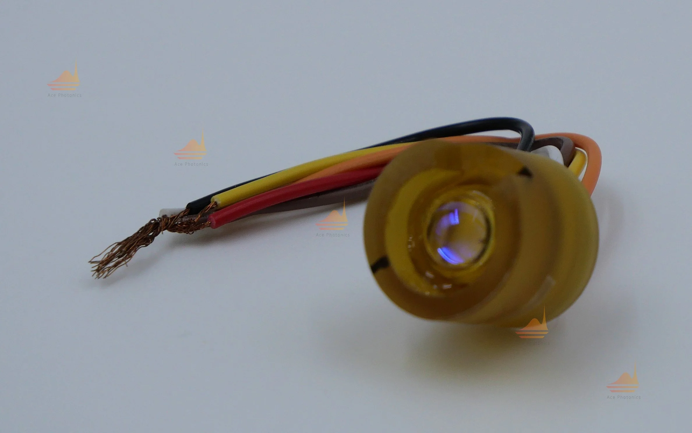
A packaged VCSEL combines the die with a housing, electrical connections and, in some cases, a window, lens, thermistor or temperature-control component.
Common formats include TO-can, SMD, ceramic, non-magnetic and custom packages.
See the available VCSEL package options.
VCSEL Array
A VCSEL array contains multiple emitters on one chip or within one assembly. Arrays can support greater total optical power or wider illumination coverage.
Array design must consider emitter spacing, uniformity, thermal behavior, beam overlap and drive architecture.
VCSEL Module
A VCSEL module can combine the laser with a driver, PCB, lens, microlens array, temperature sensor, TEC or mechanical housing.
Modules can reduce the amount of integration work required by the final system.
Explore VCSEL module solutions.
Common VCSEL Wavelengths
VCSEL wavelength is determined by the semiconductor materials and vertical-cavity design. Different wavelengths are selected for different detectors, optical filters, materials and applications.
The wavelength shown in a product name is normally a nominal value. Engineers should also confirm:
Center-wavelength tolerance
Wavelength shift with temperature
Wavelength shift with drive current
Spectral width
Side-mode behavior
Required operating temperature
Use the VCSEL wavelength selection guide when comparing wavelength and product options.
Where Are VCSELs Used?
Optical Communication
VCSELs are widely used as transmitters in short-reach optical links. Their compact size, modulation capability and compatibility with arrays make them suitable for data communication systems.
Selection factors include wavelength, modulation bandwidth, fiber type, optical power and temperature range.
3D Sensing and Time-of-Flight
A VCSEL or VCSEL array can provide infrared illumination for structured-light and time-of-flight systems.
These systems may be used for:
Depth measurement
Facial recognition
Gesture detection
Object detection
Industrial dimension measurement
Machine vision
The required product depends on sensing distance, field of view, pulse conditions, optical power and eye-safety design.
Proximity and Presence Sensing
Compact VCSELs can provide controlled optical illumination for short-range proximity, presence and reflective sensing.
Package size, beam divergence, detector response and resistance to ambient light are important design factors.
LiDAR
VCSEL arrays may be used as illumination sources in some short- and medium-range LiDAR architectures.
System designers need to evaluate pulse width, peak power, array configuration, thermal behavior, optics and applicable laser-safety requirements.
Industrial and Medical Sensing
VCSELs can support optical measurement systems that need compact size, wavelength-specific output or electronic modulation.
The laser should be selected according to the actual target material, detector, optical path and regulatory requirements rather than the general application category.
Atomic Clocks and Quantum Sensing
Single-mode VCSELs are used in compact atomic devices because their wavelength can be tuned to relevant atomic transitions and they can be integrated near small vapor cells.
For example, rubidium systems may operate near the 795 nm D1 transition, while cesium-based systems may use wavelengths near 895 nm.
Atomic magnetometers, chip-scale atomic clocks and related instruments may also require:
Controlled wavelength tuning
Single-mode output
Stable polarization
Low optical noise
Compact thermal control
Non-magnetic packaging
These requirements should be defined for the complete operating range rather than at room temperature only.
Why Non-Magnetic VCSEL Packaging Matters
Standard laser packages may contain metals or plating layers that are unsuitable near magnetically sensitive sensors.
In atomic magnetometers and other precision instruments, the material composition of the package can be as important as its dimensions.
A non-magnetic package may require evaluation of:
Header material
Lid material
Pin composition
Plating layers
Solder or conductive adhesive
Internal mechanical parts
Thermistor and TEC materials
Distance between the package and sensing cell
Non-magnetic packaging reduces one possible source of local magnetic interference, but the complete sensor assembly must still be evaluated at the system level.
Learn more about non-magnetic VCSEL packaging.
How to Select a VCSEL
The first step is to define the application and operating conditions. Avoid selecting a product based only on nominal wavelength or maximum output power.
Providing this information allows the manufacturer to evaluate both the VCSEL die and the surrounding package or module.
Frequently Asked Questions
What is a VCSEL in simple terms?
A VCSEL is a small semiconductor laser that emits light vertically from the surface of its chip instead of through the side.
Is a VCSEL a laser diode?
Yes. A VCSEL is a type of semiconductor laser diode. Its distinguishing feature is the short vertical cavity formed between two reflective DBR mirrors.
What is the difference between a VCSEL and an edge-emitting laser?
A VCSEL emits perpendicular to the wafer surface, while an edge-emitting laser emits through a side facet. The different geometry affects manufacturing, testing, beam shape, array integration and packaging.
What is the difference between a VCSEL and an LED?
A VCSEL produces coherent laser light through stimulated emission inside an optical cavity. An LED produces broader, incoherent light without a laser cavity.
Can VCSELs be tested before packaging?
Their surface-emitting structure makes electrical and optical wafer-level testing practical before individual dies are separated and packaged.
Are all VCSELs single-mode?
No. VCSELs can be designed for single-mode or multimode operation. The correct design depends on output power, beam quality, wavelength and application requirements.
What wavelengths are available?
Commercial and custom VCSELs are available at multiple visible and near-infrared wavelengths. Ace Photonics lists options around 760 nm, 790/795 nm, 850 nm, 880 nm and 890/895 nm.
Can VCSELs be supplied in non-magnetic packages?
Yes. Non-magnetic packaging can be developed for atomic magnetometers, quantum sensors and other systems that are sensitive to magnetic materials. Material and magnetic requirements should be specified during project evaluation.
VCSEL Products and Custom Support
Ace Photonics provides VCSEL dies, packaged VCSELs and application-specific modules for sensing, atomic systems and other photonic applications.
Available project options may include:
Selection by wavelength and output power
Single-mode and multimode devices
Bare die, TO-can and SMD formats
Non-magnetic package development
Custom windows and optical interfaces
Thermistor or TEC integration
Prototype and engineering sample support
Application-specific package and module development
To discuss a project, provide the application, target wavelength, output power, package preference, operating temperature and estimated quantity.
Contact Ace Photonics to request product information, engineering samples or a custom VCSEL evaluation.